Fourteenth Southeast Asian Geotechnical Conference - Hong Kong
The use of high capacity hydraulic injection piles for buildings in limestone ex-tin mining sites in Kuala Lumpur
1. INTRODUCTION
Tin mining activities in the limestone formation of Kuala Lumpur were rampant in the past. The mining activities left behind numerous ponds and remnants mainly consisting of sand and clay slime, forming a highly heterogeneous overburden on the limestone. Many ex-mining areas have become dumping grounds thus making the overburden material above the limestone more complicated.
 |
As land is getting scarce due to rapid development, previously abandoned ex-mining areas become valuable lands for developments. Conventional pile driving and bored piling encounter uncertainties and difficulties due to heterogeneous nature of the overburden materials and erratic Karstic features of limestone as illustrated in Figure 1. Gobbett & Hutchison (1973) describe the Kuala Lumpur limestone as "Upper Silurian marble, finely crystalline grey to cream, thickly bedded, variably dolomitic rock. Banded marble, saccharoidal dolomite, and pure calcitic limestone also occur". The unconfined compressive strengths (UCS) of the Kuala Lumpur limestone from a few locations are summarised in Table 1 below. |
|
Locations |
Borehole No. |
Data no. |
UCS, MPa |
|
|
Range |
Avg. |
|||
|
Sentul, site 1 |
29 |
46 |
25 - 85 |
48 |
|
Sentul, site 2 |
62 |
113 |
8 - 117 |
46 |
|
Ampang |
15 |
19 |
12 - 92 |
40 |
|
Komoo (1989) |
- |
- |
28 - 120 |
- |
|
Tan & Ch'ng (1987) |
- |
108 |
10*- 120 |
- |
|
*Low values due to failures along fractures/fissures |
||||
A typical soil profile from an ex-mining site is shown in Fig. 2. The soil is erratic, consists of very soft clayey to very loose sandy materials. Concrete blocks are encountered in some boreholes. Some abrupt increases in N values within the dump are suspected due to construction wastes. The thickness of the dump is up to 14 m in Borehole ABH-2. A test excavation carried out at the site showed the dump material highly heterogeneous, consisting of concrete blocks, wood, steel bars, metal scraps etc alongside with earth. Cavities, with vertical dimensions of up to 3 m, are encountered. A limestone overhang is suspected in borehole ABH-8 because the material above and underneath the overhang is of the same nature. |
 |
2. PILE FOUNDATION
Bored piles are usually preferred over driven piles in limestone areas due to the following concerns :
- Should there be cavities with roofs of inadequate thickness, there will be risk of collapse of the roofs if piles bear on the roofs. Bored piles can penetrate through the cavity roofs and socket a sufficient depth into the bedrock. The capacity of the bored piles will be ensured. Bored piles also overcome the problem of premature termination of driven piles on hard lenses, floaters or overhangs above bedrock.
- Due to erratic limestone rock surface, piles tend to deviate during driving although provision of pile shoes and proper control of driving energy may be able to reduce this phenomenon. Pile deviation results in excessive pile length and pile damages. Quite often the integrity of piles can be affected without showing visible signs of damages.
- Driving of piles is not allowed in many populated parts of Kuala Lumpur due to noise pollution.
However, bored pile solution is costly and slow in construction compared to driven piles. Stringent construction control is required to ensure the quality of bored piles. Due to the nature of overburden material and limestone bedrock, difficulties can be encountered :
- Many ex-mining areas become dump grounds. Boring would be frequently hindered by debris in the dump such as concrete blocks, steel bars, metal scraps etc
- Bored holes are not stable when slime or very soft/very loose material, a common feature of ex-mining remnants (such as those in boreholes ABH-5 & -6, Figure 2), is encountered. Although casing can be provided to overcome this problem, collapses of bored holes are still possible as slimy soil can enter the casing through gaps between the casing and uneven limestone rock surface. There were cases where grouting treatments were needed prior to bored pile construction due to the existence of slimy material.
3. JACK-IN PILING SYSTEM
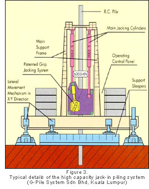
In Malaysia, jack-in piling system was first developed about 12 years ago. It started with a low jacking capacity of 20 tonnes for small RC piles of 10 tonnes working load as an alternative to the tanalised timber piles. The jack-in capacity was increased to 60 tonnes and later 90 tonnes.
In the mid-nineties, there were enquiries from the consultants and the government authorities to look into developing a jacking system that could go beyond the 100 tonne capacity. Such a system was found in China and the jacking capacity was 400 tonnes and later increased to 600 tonnes. It handles square concrete, 250 mm to 550 mm in size; circular concrete spun piles, 0.3 m to 0.6 m diameter, and steel H-piles. The working capacity of piles installed is similar to normal driven piles, in the range of 1000 kN to 2500 kN if ground condition permits. Figure 3 illustrates the set-up of the jacking system. The specifications of the system are given in Table 2.
 |
In view of the above shortcomings and difficulties associated with bored piles and driven piles, pile jack-in piling method offers an alternative.
|
| Table 2. Specifications of a 6000kN capacity jack-in piling system | |||
|
Item |
Unit |
Value |
|
|
Main Body Movement |
X-Direction |
m |
3 |
|
Y-Direction |
m |
0.55 |
|
|
Maximum Turning Angle |
Degree |
20 |
|
|
X-Y Direction Movement Speed |
Forward |
M/min |
1.8 |
|
Reverse |
M/min |
4 |
|
|
Pile Size |
Maximum |
m |
0.55x0.55 |
|
Minimum |
m |
0.30x0.30 |
|
|
Bearing Pressure |
Long Sleeper |
Ton/m2 |
14.2 |
|
Short Sleeper |
Ton/m2 |
17.5 |
|
|
System |
Dimension (L x W x H) |
m |
11.1x10x9.1 |
|
Self Weight |
ton |
200 |
|
|
Counter Weight |
ton |
430 |
|
4. DESIGN CONSIDERATIONS
During pile installation, the jack-in force for every 0.3 m (1ft) penetration is recorded. A 'set' is taken when the jack-in force is picking up indicating the pile has reached a bearing stratum. Normally, the pile is jacked to sustain a force of 2DL. This mechanism is similar to a static load test conducted in an accelerated manner on the pile. The set adopted is verified by pile load tests. Since every pile is installed in the same manner, the capacity of each pile is verified. More important, in erratic limestone bedrock, a good contact between the pile tip and bedrock is ensured by the high jack-in force. The problems of pile deviation and damages due to erratic limestone surface and hard driving experienced by pile driving are significantly reduced.
4.2 Premature pile terminationThe concern of premature pile termination arises due to the existence of floating hard lenses (high N value material). The problem can be overcome by applying a higher jack-in force when necessary.
With the help of boreholes, locations of hard lenses can be first identified. 'Pilot' piles can be installed at such locations to see if pile penetration is really a problem. Most of the time, hard lenses or boulders can be penetrated or pushed aside with some increase in jack-in force. When a thicker hard lens is encountered, jack-in force of up to 2.5DL or above should be tried. When proven futile, although quite unlikely, pre-boring can be introduced.
Premature pile termination is also a concern when limestone floaters and overhangs are encountered. In a previously mined site, floaters would be exposed during mining operation and sank to bedrock after the materials underneath had been mined; Overhangs are normally cliff-like rather than in the form of a 'diving board'. This can be observed from the exposed limestone in various parts of Kuala Lumpur and in Gobbett & Hutchison (1973).
Boreholes can be carried out to identity the feature of limestone and subsoil condition when pile length varies significantly within a pile group. If the material underneath the shorter piles is less competent, an appropriate remedy that may include downgrading of pile capacity with respect to the strength of the material underneath is required in order to control differential settlement. Wyllie (1992) suggests performing pile group analysis to ensure the load distribution amongst the piles to be within DL. When the difference in pile lengths is significant between adjacent pile groups, differential settlement amongst the pile groups should be assessed. 4.3 CavitiesCavities are a common feature in limestone. They associate with few types of failure mechanisms, namely local crushing, punching shear failure and bending failure of cavity roofs.
4.3 Local crushingKaderabek & Reynolds (1981) highlight the possibility of local crushing failure when contact pressure exceeds the confined compressive strength of limestone. They further suggest that factor safety of 2 is available when the unconfined compressive strength (UCS) of the limestone is not exceeded.
This failure is not a concern for jack-in piles as high jack-in forces verify the contact between pile toes and limestone.
4.3.2 Punching shear failureSince every single pile is jacked to sustain a jack-in force of up to 2DL, The pile should punch through any weak roof and thus rule out the possibility of punching shear failure. In the case of pile groups, the possibility of punching shear failure can be assessed using the similar approach for the calculation of pile group effect. With adequate pile spacing, pile group effect can be ignored simply because the perimeter of the pile group is larger than adding up the circumferences of all individual piles in the pile group. A spacing of 3 pile diameters is adequate for pile groups consisting of up to 4 piles arranged in a quadrilateral pattern. For larger pile groups, pile spacing should be assessed according.
4.3.3 Bending failureThe bending moment (M) and tensile stress (T) of a cavity roof can be evaluated by the methods of Roark as suggested by Wyllie (1992). The cavity roof is assumed circular in shape and simply supported around the edges.
|
|
||
|
||
|
|
||
where Q = load on the roof; P = Poisson's ratio of the limestone; r = radius of the cavity; ro = a parameter depends on the radius of loaded area and thickness of the roof.
|
|
||
|
||
|
|
||
where D = equivalent diameter of the loaded area. The authors assume the loaded area is the area enclosed by the pile group; H = thickness of the cavity roof.
Tensile strength tests for rock are not commonly carried out, not to mention rock masses. Hoek (1983) approximates the tensile strength of rock mass by:
|
|
||
|
||
|
|
||
The tensile strengths of carbonate rock (e.g. dolomite, limestone and marble) masses are given in Table 3.
Kaderabek & Reynolds (1981) report that full-scale load tests were carried out to induce a beam tension failure. Such a failure did not occur even the maximum tensile stress, based on theoretically computation (by Roark's method) exceeded by a factor of 2 the tensile strength determined by laboratory splitting tests on 4" core samples. They further remark beam tension failure has not been reported in south Florida area. The median strength of UCS of the Miami limestone is 1.5 MPa (Wyllie 1992).
Table
3. Tensile strength of carbonate rocks expressed
as percentage of UCS of intact rock samples (Hoek
1983).
Description
Empirical
constants
qt(m)
/qu(r)
Intact
rock samples
m=7, s=1
14%
Very
good quality rock mass, joints 1 - 3m
m=3.5, s=0.1
2.8%
Good
quality rock mass, joints 1 - 3m
m=0.7, s=0.004
0.6%
Fair
quality rock mass, joints 0.3 - 1m
m=0.14, s=.0001
0.07%
Poor
quality rock mass, joints 0.03 - 0.5m
m=0.04,
s=0.00001
0.02%
| Table 3. Tensile strength of carbonate rocks expressed as percentage of UCS of intact rock samples (Hoek 1983). | ||
|
Description |
Empirical constants |
qt(m) /qu(r) |
|
Intact rock samples |
m=7, s=1 |
14% |
|
Very good quality rock mass, joints 1 - 3m |
m=3.5, s=0.1 |
2.8% |
|
Good quality rock mass, joints 1 - 3m |
m=0.7, s=0.004 |
0.6% |
|
Fair quality rock mass, joints 0.3 - 1m |
m=0.14, s=.0001 |
0.07% |
|
Poor quality rock mass, joints 0.03 - 0.5m |
m=0.04, s=0.00001 |
0.02% |
Roof failure by bending may not be such a concern. The shape of small caves in limestone is more of arch then flat slab as observed by Wilford (1964), as illustrated in Figure 4. Equations (1) and (2) tend to overestimate the bending moment and tensile stress experienced by cavity roofs significantly for an arch shape cavity where loads are mainly converted into compression on the arch.
Nonetheless, under jacking force of up to 2DL on every pile installed, competency of cavity roofs is verified in a manner that can only be superseded by a static load test conducted on the pile. Since the number of load tests is limited, jack-in piling method implements a verification process far more reliable than bored piles and conventional pile driving.
Using equations (1) to (3) above, the tensile stresses experienced by the roofs of cavities of various radii and roof thickness, supporting a 4-pile group are tabulated in Table 4.
It can be observed that tensile stress decrease rapidly with cavity roof thickness H. When H exceeds 5 m, tensile stress reduces to less than 0.35 MPa for cavities of up to 10m in diameter. This tensile stress is about 0.8% of the average UCS of Kuala Lumpur limestone of 45 MPa.
Table
4. Tensile strength (in kPa) of cavity roofs
supporting a quadrilateral patterned 4-pile
group. Piles are 0.4 m square piles at 1.2 m
spacing. Column load is assumed 4DL, DL being
1500 kN.
Roof
thick-ness, H(m)
Cavity
radius, r (m)
2
3
5
1
5173
7165
8995
2
1380
1742
2200
3
527
688
891
4
250
340
454
5
133
191
265
| Table 4. Tensile strength (in kPa) of cavity roofs supporting a quadrilateral patterned 4-pile group. Piles are 0.4 m square piles at 1.2 m spacing. Column load is assumed 4DL, DL being 1500 kN. | |||
|
Roof thick-ness, H(m) |
Cavity radius, r (m) |
||
|
2 |
3 |
5 |
|
|
1 |
5173 |
7165 |
8995 |
|
2 |
1380 |
1742 |
2200 |
|
3 |
527 |
688 |
891 |
|
4 |
250 |
340 |
454 |
|
5 |
133 |
191 |
265 |